Frequently Asked Questions
The following is a variety of questions that are frequently asked by many of our customers over the past years. It is our intention to post them here for the benefit of all users.
Technical Questions
What is the A side, B side configuration of PCI
cards and what VIO version should one order?
Which
of the PCI right angle extenders will fit in a 1U / 2U chassis?
What is the A side, B side configuration of AGP cards
and what VDDq version should one order?
Which
of the AGP right angle extenders will fit in a 1U / 2U chassis?
What is the life cycle of the PCI / AGP extenders?
What is the Board ID and Vender ID of a PCI or AGP card
?
What is the maximum specified power
consumption of a PCI expansion card?
What is
the maximum specified power consumption of an AGP card?
What is the pin out of the PCI connector?
What is the pin out of the AGP connector?
How to set up the system for remote control of the
PCI/AGP bus isolation extenders via software command?
How to compose the
suffix for the part number of the multiple slot risers?
How to select a
right angle riser to fit properly into an existing chassis cutout?
General Questions
How does one place an order ?
What are the best shipping methods ?
How does one buy?
What is the repair policy offered?
How does one buy spare parts?
What does it take to get a custom PCI / AGP extender card
made?
Do you offer free samples or
boards for evaluation?
ˇ@
Technical Questions
What is the A side, B side configuration of PCI cards
and what VIO version should one order?
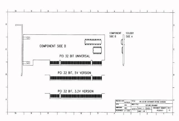
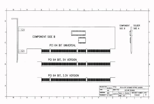
The Component side of the PCI card is the B side, and the solder side of the card is the A side. If looking from the back of the system chassis, the B side is on the right and the A side is on the left. The PCI bus is specified to have 5V, 3.3V, 12V, -12V and VIO on the bus. The VIO is intended as the VCC power to the PCI bus interface controller ICs. The VIO could be either 5V or 3.3V, depending on the motherboard PCI expansion slot design. The PCI expansion slot connector is divided into two sections by a plastic divider called the "key". If the key of the PCI expansion slot connector is located near the back of the chassis then the VIO for that slot is 3.3V. If the key is located closer to the center of the motherboard, then the VIO for that slot is 5V. Most of the 32 bit PCI slots are designed to be VIO=5V. For the 64 bit PCI slot, an additional key is placed between the 32 bit section and the 64 bit extension, dividing the connector into 3 sections. However, the identification of the VIO for the 64 bit slot is the same as the 32 bit slot. For a slower clock(33MHz) PCI 64 bit slot, the VIO is usually 5V, for a faster clock(66MHz) PCI 64 bit slot, the VIO is usually 3.3V.
If the user's PCI I/O board, gold finger is cut for a universal configuration, then the board is not using the VIO power for it's interface controller chip. The I/O board is using either the 3.3V or the 5V, directly off the PCI bus. However, since there is no universal PCI connector, when placing an order for the extender with universal key cut, the user still needs to specify either the 5V or the 3.3V version. This way the appropriate connector will be used and the key on the gold finger will be cut in the proper place. To order the PCI extender with universal cut, we would recommend specifying the connector on top to be 5V for the 32 bit PCI, and 3.3V for the 64 bit PCI. For example, PCITX4-?-B-U5, or PCITX8-?-B-U3.
Warning, one could order the extender in such a way that allows a
PCI 5V card to connect to the PCI 3.3V slot, or vise versa, but in operation it
may not work, and in rare cases, it may cause damage to the I/O card and/or the
motherboard. Please see the following drawings for the PCI keying
configurations.
Which of the PCI right angle extenders will fit
in a 1U / 2U chassis?
The PCITX4-1, PCITX4-2, PCITX8-1 and PCITX8-2 are designed to fit in the 2U chassis. All the others, except the PCITX4-8 and the PCITX8-7, are the shorter versions that can also be used in the 2U chassis. The PCITX4-5, PCITX4-6, PCITX8-5 and the PCITX8-6 are currently the shortest right angle riser cards and they are designed for the 1U chassis. Please see the following PCITX4 and PCITX8 comparison chart.
PCITX4 Extender Comparison Chart
| P/N | WIDTH | OVERALL HEIGHT | CONN HEIGHT -A & -B |
| PCITX4-1 | 3.54" | 1.28" | 1.03" |
| PCITX4-2 | 3.54" | 2.08" | 1.83" |
| PCITX4-3 | 3.54" | 1.10" | 0.90" |
| PCITX4-4 | 3.54" | 1.90" | 1.70" |
| PCITX4-5 | 3.54" | 0.75" | 0.55" |
| PCITX4-6 | 3.54" | 0.96" | 0.76" |
| PCITX4-7 | 3.54" | 1.89" | 1.59" |
| PCITX4-8 | 3.54" | 2.64" | 2.39" |
| PCITX4-9 | 3.54" | 1.75" | 1.50" |
PCITX8 Extender Comparison Chart
| P/N | WIDTH | OVERALL HEIGHT | CONN HEIGHT -B | CONN HEIGHT -A |
| PCITX8-1* | 5.24" | 1.28" | 1.03" | 0.63" |
| PCITX8-2* | 5.24" | 2.08" | 1.83" | 1.43" |
| PCITX8-3* | 5.32" | 1.08" | 0.88" | -- |
| PCITX8-4** | 5.24" | 0.57" | -- | 0.43" |
| PCITX8-5 | 5.24" | 0.75" | -- | 0.55" |
| PCITX8-6* | 5.24" | 0.96" | 0.76" | -- |
| PCITX8-7* | 5.24" | 2.58" | 2.32" | 1.92" |
| PCITX8-31 | 5.32" | 2.72" | 0.92", 1.72", 2.52" | -- |
* Extender that supports the PCIX mode and allow VIO conversion.
** Does not support VIO conversion.
What is the A side, B side configuration of AGP
cards and what Vddq version should one order?
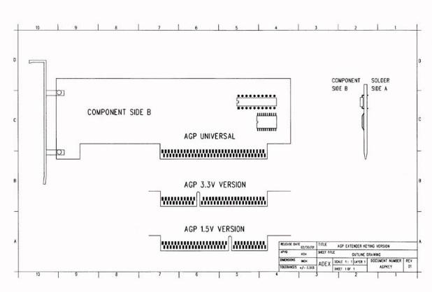
The Component side of the AGP card is the B side, and the solder side of the card is the A side. If looking from the back of the system chassis, the B side is on the right and the A side is on the left. The AGP bus is specified to have 5V, 3.3V, 12V and Vddq on the bus. The Vddq is intended as the VCC power to the AGP bus interface controller ICs. The Vddq could be either 3.3V or 1.5V, depending on the motherboard AGP expansion slot design. The AGP expansion slot connector is divided into two sections by a plastic divider called the "key". If the key of the AGP expansion slot connector is located near the back of the chassis then the Vddq for that slot is 3.3V. If the key is located closer to the center of the motherboard, then the Vddq for that slot is 1.5V. Most of the earlier 1X and 2X AGP slot was designed to be Vddq=3.3V. For the newer motherboards, the AGP slot could be up to 4X mode, and the Vddq could be keyed for 1.5V. Some motherboards may have also used the universal AGP connector. The universal AGP connector, as specified in the AGP specification, has no dividing plastic "key". This means the universal AGP card has no cut on the gold finger, which is the opposite of the key cuts for the PCI universal I/O card.
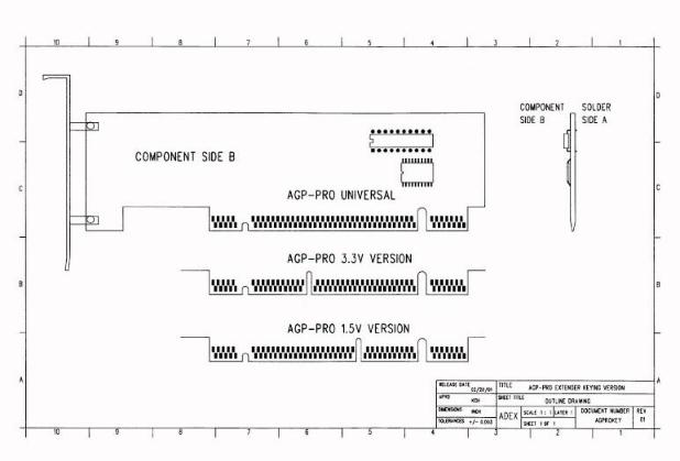
The AGP-PRO card is intended for higher performance and a higher power AGP card. Two extra sections are added to the AGP slot. These extra sections consist mainly of additional 12V and 3.3V power and ground. The AGP-PRO connector has an extra shorter key. The shorter key prevents an AGP-PRO card to be inserted into an AGP connector. The AGP-PRO has the same 1.5V, 3.3V and universal configuration as specified in the AGP specification
If the user's AGP card gold finger is cut for a universal configuration, then the board is not using the Vddq power for it's interface controller chip. The card is using either the 3.3V or the 1.5V directly off the AGP bus. When placing an order for the extender, the user should specify either the 3.3V, 1.5V or the universal version. This way the appropriate connector will be used and the key on the gold finger will be cut properly.
Warning, one could order the extender in such a way that allows an
AGP 3.3V card to connect to the AGP 1.5V slot, or vise versa, but in operation
it may not work, and in rare cases, it may cause damage to the AGP card and/or
the motherboard. Please see the following drawings for the AGP and AGP-PRO
keying configurations.
Which of the AGP right angle extenders will fit
in a 1U / 2U chassis?
All the AGPRX4 and AGPTX4 extenders, except the AGPTX4-3, can be used in the 2U chassis. The AGPTX4-5 and the AGPTX4-6 are designed for the 1U chassis. Please see the following AGPRX4 / AGPTX4 comparison chart.
| P/N | WIDTH | OVERALL HEIGHT | CONN HEIGHT -B | CONN HEIGHT -A |
| AGPRX4-1* | 3.74" | 1.76" | 1.515" | - - |
| AGPRX4-2* | 3.74" | 2.02" | 1.771" | - - |
| AGPRX4-4* | 3.74" | 2.434" | 2.184" | - - |
| AGPTX4-5 | 3.54" | 0.975" | 0.786" | 0.55" |
| AGPRX4-6* | 3.75" | 1.15" | 0.95" | - - |
| AGPTX4-7* | 3.75" | 2.08" | 1.83" | 1.59" |
| AGPRX4-8* | 3.74" | 2.13" | 1.88" | 1.643" |
| AGPRX4-9* | 3.54" | 2.13" | - - | 1.88" |
| AGPRX4-11* | 3.75" | 1.104" | 0.904" | - - |
* Designed to AGP 8X specification.
What is the life cycle of the PCI / AGP extenders ?
The extenders can be used either to prolong the life of the connector, on the motherboard or to prolong the gold finger of the I/O card. Therefore, either the connector or the gold finger of the extender, will wear out. For most of the straight extenders, the straddle mount connectors are custom made, heavy duty connectors. The life cycle of these connectors are about 1500 to 2000 insertion cycles. If the insertion and removal are aided by mechanical fixtures, the life cycle could be 3000 to 4000 cycles and higher. The gold finger on most of the extenders are plated with 50 micro inches of hard gold, with 100 micro inches of nickel underlayer. It is designed to withstand 1500 to 2000 insertion cycles or more.
What is the Board ID and Vendor ID of a PCI or
AGP card ?
The Vendor ID (VID) is used to identify the manufacturer of the controller IC, and the Board ID (BID) is used to identify the type of I/O function for the controller IC (or board). The VID and BID numbers consist of 4 hexadecimal digits (16 bits). These numbers are maintained by the PCI Special Interest Group. The VID and the BID numbers are usually embedded in the first two registers of every PCI and AGP boards. One may also check the following website to see a list of these numbers: http://www.yourvote.com/pci/ .
What is the maximum specified power consumption
of a PCI expansion card?
5A for 5V, 8 pins (add 5 pins for VIO=5V in 32 bit PCI bus; add 6 more pins for PCI 64 bit bus).
7.6A for 3.3V, 12 pins (add 5 pins for VIO=3.3V in 32 bit PCI bus; add 6 more pins for PCI 64 bit bus).
500 mA for 12V, 1 pin.
100mA for -12V, 1 pin.
375mA for 3.3Vaux, 1 pin.
What is the maximum specified power consumption
of an AGP card?
6A for 3.3V, 10 pins for AGP (7.6 A for AGP-PRO, 20 pins).
1A for 12V, 1 pin for AGP (9.2A for AGP-PRO, 13 pins).
2A for 5V, 2 pins.
8A for Vddq, 10 pins (can be either 3.3V or 1.5V)
Approximately 100 to 375 mA for 3.3Vaux, 2 pins (may be 1 pin, if the expansion slot is designed for 3.3V or 1.5V instead of the universal)
What is the pin out of the PCI connector?
Please download the PCI64PO.PDF file to see the PCI 32 and PCI 64 bit connector pinout.
What is the pin out of the AGP connector?
Please download the AGPROPO.PDF file to see the AGP and AGP-PRO connector pinout.
The following two zipped files detail the necessary hardware and software conditions for remote control of the bus isolation extenders via software. For PCI cards, use the PCIINIT.zip file. For AGP cards, use the AGPINIT.zip file.
How to compose the suffix for the part number of the
multiple slot risers?
The suffix of the multiple slot risers is composed of three groups of numbers, -XYZ-ABC-W/N. These numbers have slight different meanings to each type of riser cards, as defined in the following.
PAPTX-PCI (PAPTXP) and PAPTX-AGP (PAPTXA):
The PAPTXP and the PAPTXA are combo risers that are capable of up to two 64
bit PCI connectors and 1 AGP connector. The PCI connectors on the riser can be
either 32 bit or 64 bit connectors. The AGP connector can be either a 1X/2X
(3.3V), 4X/8X (1.5V) or an universal (no key) connector. The PAPTXP is deigned
to be inserted into a PCI-32 or a PCI-64 slot on the motherboard. The PAPTXA is
designed to be inserted into a AGP slot.
-XYZ identifies the bus
size of the three connectors, counting from top to bottom. The X and Z can be
8, 4 or 0, which means 64 bit, 32 bit or no PCI coonector. The Y can be 1 or
0, which means 1 or no AGP connector . For example, -818 means a 64 bit PCI
connector at the top position , a AGP connector at the middle and a 64 bit PCI
connector at the bottom positions. The -414 means 32 bit PCI connectors at the
top and bottom positions. A zero in any of the XYZ suffix, means no connector
at that position.
-ABC identifies the VIO voltage selection of the
connectors. TheA and C can be 3, 5 or 0, which means the PCI VIO is 3.3V, 5V or
none. This should correspond to the connectors defined in the XZ suffix above.
The B can be U, 3, 1 or 0, which means an universal, 3.3V, 1.5V or none for the
AGP connector. For example, -313 means 3.3V, 1.5V, 3.3V for each of the
connectors specified in -XYZ position. The -515 means 5V, 1.5V, 5V. The 3U3
means 3.3V, Universal, 3.3V. The ABC suffix specifies which keyed connector
types to be used. The Universal for the AGP means a connector with no blocking
plastic key. The 3.3V keyed AGP connector is used for the 1X or 2X cards. The
1.5V keyed AGP connector is used for the 4X or 8X cards. A zero in any of the
positions means no voltage configuration because there is no connector. These
multiple risers allow the PCI connector VIO voltage to be different than the PCI
slot VIO, where the riser or the cables plug in.
-W/N means the
cable lengths associated with the riser. The W reflects the wide cable in
inches. The N reflects the narrow cable in inches. The wide cable carries all
the signals from a PCI slot on the motherboard to the riser, and the narrow
cable carries only the necessary signals from another PCI slot to the riser.
For example -1/3 means 1" wide cable and 3" narrow cable. In PAPTX-AGP,
the two PCI motherboard slots used by the cables, must have common bus signals
coming from a single PCI bridge controller channel on the motherboard. Both
slots must run at the same clock speed and have same VIO voltage. In PAPTX-PCI,
the AGP signals come from a AGP riser card behind the riser, so only one narrow
cable is needed for the 2nd PCI connector. The 2nd PCI motherboard slot used
by the narrow cable must have common bus signals as the PCI slot where the riser
plugs in.
PCITX3N1 and PCITX3S1:
The PCITX3N1 and the PCITX3S1 are three slot PCI risers with different bus
groupings. Both of these risers can be inserted into a PCI-64 or a PCI-32 slot
on the motherboard.
-XYZ means the bus size of the three connectors,
counting from top to bottom. The X, Y and Z can be 8, 4 or 0, which means
PCI-64 bit, PCI-32 bit or no connector. For example, -888 means three 64 bit
PCI connectors. The -444 means three 32 bit PCI connectors. The -884 means
two 64 bit PCI connectors at the top and one PCI 32 bit connector at the bottom.
A zero in any of the XYZ suffix, means no connector at that position.
-ABC
means the VIO voltage selection of the connectors. The A, B and C can be 5, 3
or 0, which means 5V, 3.3V or none. For example, -333 means 3.3V, 3.3V, 3.3V for
each of the connectors specified in -XYZ position. The -555 means 5V, 5V, 5V.
The -335 means 3.3V, 3.3V, 5V. A zero in any of the positions means no voltage
configuration because there is no connector. These multiple risers allow the
PCI connector VIO voltage to be different than the PCI slot VIO where the riser
or the cables are plugged in.
-W/N means the cable lengths
associated with the riser. The W reflects the wide cable in inches. The N
reflects the narrow cable in inches. The wide cable carries all the signals
from a PCI slot on the motherboard to the riser, and the narrow cable carries
only the necessary signals from another PCI slot to the riser. For example
-2/4 means 2" wide cable and 4" narrow cable. In PCITX3N1,
the narrow cable need to be inserted to a PCI slot that has common bus signals
as the slot where the riser plugs in. The wide cable can be inserted into
another slot that is independent from the other two. In the PCITX3S1,
the two cables need to be plug into two motherboard slots that have common bus
signals coming from a single PCI bridge controller channel on the motherboard.
Both slots must run at the same clock speed and have same VIO voltage.
PEPRX16:
The PEPRX16 is a combo risers that are capable of up to two 64 bit PCI
connectors and 1 PCI Express connector. The PCI connectors on the riser can be
either 32 bit or 64 bit connectors. The PCI EXpress (PE) connector can be
either a X16, X8, X4 or X1 connector. The PEPRX16 is deigned to be inserted
into a PE-X16 slot on the motherboard. However, the gold finger area could be
cut down to fit into a X8, X4 or X1 PE slot.
-XYZ identifies the bus
size of the three connectors, counting from top to bottom. The X and Z can be
8, 4 or 0, which means 64 bit, 32 bit or no PCI coonector. The Y can be x ,8,
4, 1 or 0, which means X16, X8, X4, X1 or no PE connector . For example, -8x8
means a 64 bit PCI at the top position , PE-X16 at the middle and a 64 bit PCI
connector at the bottom positions. The -414 means 32 bit PCI connectors at the
top and bottom, with a PE-X1 connector at the middle positions. A zero in any
of the XYZ suffix, means no connector at that position.
-ABC
identifies the VIO voltage selection for the PCI connectors and PE gold finger
size. The A and C can be 3, 5 or 0, which means the PCI VIO is 3.3V, 5V or
none. This should correspond to the connectors defined in the XZ suffix above.
Since there is noVIO association with the PCI Express cards, the B suffix here
is used to specify the size of the PE gold finger area. The B can be 0, 8, 4 or
1, which means no change (X16) to the gold finger, or cut down to PE X8, X4 or
X1 size. For example, -303 means 3.3V, X16, 3.3V for each of the connectors
specified in -XYZ position. The -515 means 5V, X1, 5V. This multiple riser
allows the PCI connector VIO voltage to be different than the PCI slot VIO where
the cables plug in.
-W/N means the cable lengths associated with the
riser. The W reflects the wide cable in inches. The N reflects the narrow
cable in inches. The wide cable carries all the signals from a PCI slot on the
motherboard to the riser, and the narrow cable carries only the necessary
signals from another PCI slot to the riser. For example -1/2 means 1"
wide cable and 2" narrow cable. The two PCI slots that are being used,
must have common bus signals coming from a single PCI bridge controller channel
on the motherboard. Both slots must run at the same clock speed and have same
VIO voltage.
EPPRX16:
The EPPRX16 is a combo risers that are capable of up to two 64 bit PCI
connectors and 1 PCI Express connector. The PCI connectors on the riser can be
either 32 bit or 64 bit connectors. The PCI EXpress (PE) connector can be
either a X16, X8, X4 or X1 connector. The EPPRX16 is designed to be inserted
into a PE-X16 slot on the motherboard. However, the gold finger area could be
cut down to fit into a X8, X4 or X1 PE slot. The EPPRX16 is similar to the
PEPRX16, but has the top two connector positions swapped.
-XYZ
identifies the bus size of the three connectors, counting from top to bottom.
The Y and Z can be 8, 4 or 0, which means 64 bit, 32 bit or no PCI coonector.
The X can be x ,8, 4, 1 or 0, which means X16, X8, X4, X1 or no PE connector .
For example, -x88 means a PE-X16 at the top position , and two 64 bit PCI
connectors at the lower positions. The -144 means one PE-X1 at the top and
two32 bit PCI connectors at the middle and bottom positions. A zero in any of
the XYZ suffix, means no connector at that position.
-ABC identifies
the VIO voltage selection of the PCI connectors and the riser's PE gold finger
size. The B and C can be 3, 5 or 0, which means the PCI VIO is 3.3V, 5V or
none. This should correspond to the connectors defined in the YZ suffix above.
Since there is noVIO association with the PCI Express cards, the A suffix here
is used to specify the size of the PE gold finger area. The A can be 0, 8, 4 or
1, which means no change (X16) to the gold finger, or cut down to PE X8, X4 or
X1 size. For example, -033 means X16, 3.3V, 3.3V for each of the connectors
specified in -XYZ position. The -155 means X1, 5V, 5V. This multiple riser
allows the PCI connector VIO voltage to be different than the PCI slot VIO
where the cables plug in.
-W/N means the cable lengths associated
with the riser. The W reflects the wide cable in inches. The N reflects the
narrow cable in inches. The wide cable carries all the signals from a PCI slot
on the motherboard to the riser, and the narrow cable carries only the necessary
signals from another PCI slot to the riser. For example -1/2 means 1"
wide cable and 2" narrow cable. The two PCI slots that are being used,
must have common bus signals coming from a single PCI bridge controller channel
on the motherboard. Both slots must run at the same clock speed and have same
VIO voltage.
EPERXP:
The EPERXP is a combo risers that are capable of up to two PCI Express
connectors and 1 PCI connector. The PCI connector on the riser can be either a
32 bit or a 64 bit connector. The PCI Express (PE) connectors can be either
X16, X8, X4 or X1 connectors. The EPERXP is designed to be inserted into a
PCI-32 or a PCI-64 slot on the motherboard.
-XYZ identifies the
bus sizes of the three connectors, counting from top to bottom. The X and Z can
be x, 8, 4, 1 or 0, which means X16, X8, X4, X1 or no PCI Express connector.
The Y can be 8, 4 or 0, which means 64 bit, 32 bit or no PCI connector. For
example, -x81 means a PE-X16 at the top, a 64 bit PCI connector at the middle
and a PE-X1 connector at the bottom positions. A zero in any of the XYZ suffix,
means no connector at that position.
-ABC identifies the VIO voltage
selection for the PCI connector or the size of the PE paddle boards. The B can
be 3, 5 or 0, which means the PCI VIO is 3.3V, 5V or none. This should
correspond to the connector defined in the Y suffix above. The A and C can be
0, 8, 4 or 1, which means X16, X8, X4 or X1 PE size paddle board at the end of
each cable. For example, -031 means 3.3V PCI connector with a X16 and a X1
cable attached. This multiple riser allows the PCI connector VIO voltage to be
different than the PCI slot VIO where the riser plugs in..
-W/N
means the cable lengths associated with the riser. The W reflects the cable
length of the paddle board attached to the top PE connector, in inches. The N
reflects the cable length of the paddle board attached to the bottom connector,
in inches. For example -2/1 means 2" top cable and 1" bottom cable.
How to select a right angle riser to fit properly
into an existing chassis cutout?
There are many ways to go about making a selection. One approach would be to follow the below steps:
1. Put your I/O card into the desired chassis cutout, without a riser.
2. Measure the distance from the center of the I/O card's PCB to the top of the motherboard.
3. Subtract that distance by 0.3" for PCI slot, 0.25" for AGP slot or 0.14" for PCI-Express slot. The result should be the proper connector center height of a right angle riser card.
4. Select a riser card with a connector center height that is the closest match to the calculated height (in step #3). One can use the riser comparison chart for easier selections.
ˇ@
General Questions
We suggest you place an order by faxing us at: (886) 3-5278722, or by emailing us at: extenders@pmasia.com. Order quantity change will incur a price adjustment based on actual quantity ordered or shipped.
What are the best shipping methods ?
International shipping, we suggest you use Fedex, UPS, DHL, Airborne or Emery. To use one of these carriers, we need you to provide your company's shipper account number as we are unable to estimate the cost of tax and duty, where applicable. If it is inconvenient to use your own company's account number to ship against, we recommend you have us ship by way of DHL Collect (they will collect the shipping fees, tax and duty fees upon delivery). Other options for oversea shipping are: Express Mail or Global Priority Mail, through the US postal carrier. Express Mail delivery is generally within one week. Global Priority Mail is the least expensive method, generally takes 1-2 weeks delivery time but only delivers to certain areas and is not guaranteed (no signature is required).
For our first time overseas customers, we prefer to have your orders prepaid by bank transfer (T/T) or credit card (Visa/Master card).
What is the repair policy offered?
If you have a board that you wish to have repaired, you may contact us for an RMA (return merchandise authorization) number. We offer a repair service as a courtesy to our customers. The flat rate for repairs to bus isolation extenders is $35.00 per board plus shipping costs. This does not include the cost for new connectors should they need to be replaced. If your board needs a new connector, the additional cost would be $18.00 each.
You may purchase spare parts directly from us. Please contact us for correct part numbers and pricing on all spare parts.
What does it take to get a custom extender card
made?
To obtain a quote for a custom designed card, we would need you to provide us with the necessary details of height, dimension, and mechanical information. We would need to know your desired quantity and preferred lead time. The average lead time for a custom designed board is typically 4 weeks. If you wish to have one of our existing boards modified, the cost would then be based on a minimum order of 100 pieces. The lead time would generally be 2-3 weeks. The price would be based on our list price for the first 100 boards.
Do you offer free samples or boards for evaluation?
We do not offer free board samples.